Tuesday, March 17, 2015

11th Week: "Three-Phase Circuits"

"Balanced Three-Phase Voltages"


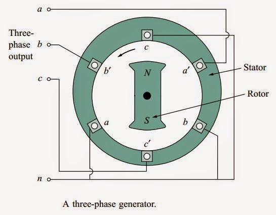
Three-phase voltages are often produced with a three-phase ac generator or alternator whose cross-sectional view is shown below,


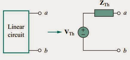
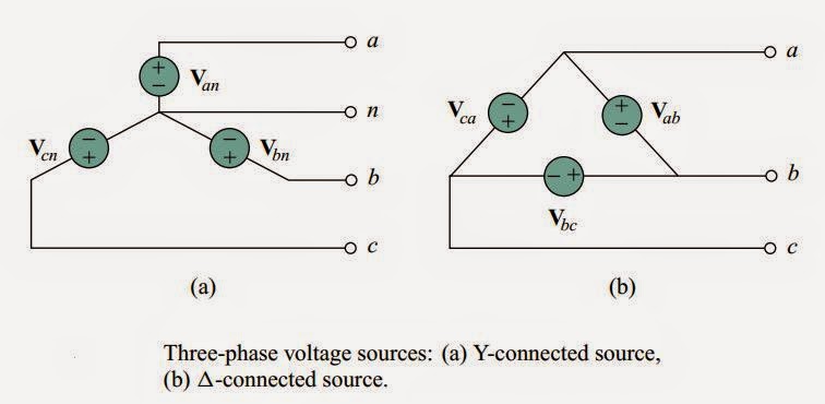
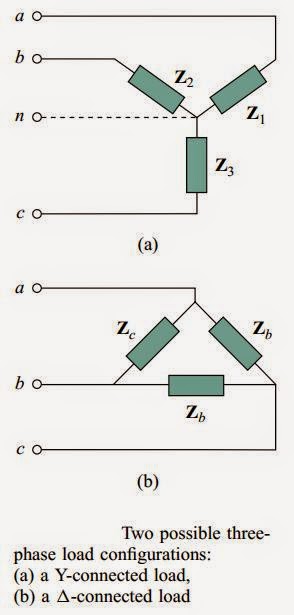
The voltage sources can be either wye-connected as shown in Fig.(a) or delta-connected as in Fig (b).


Balanced phase voltages are equal in magnitude and are out
of phase with each other by 120◦.


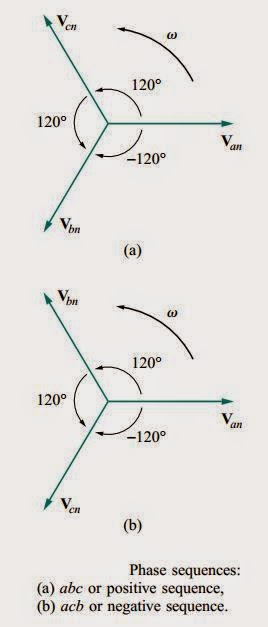
The phase sequence is the time order in which the voltages pass through their respective maximum values.


A balanced load is one in which the phase impedances
are equal in magnitude and in phase.


Types of Connections:
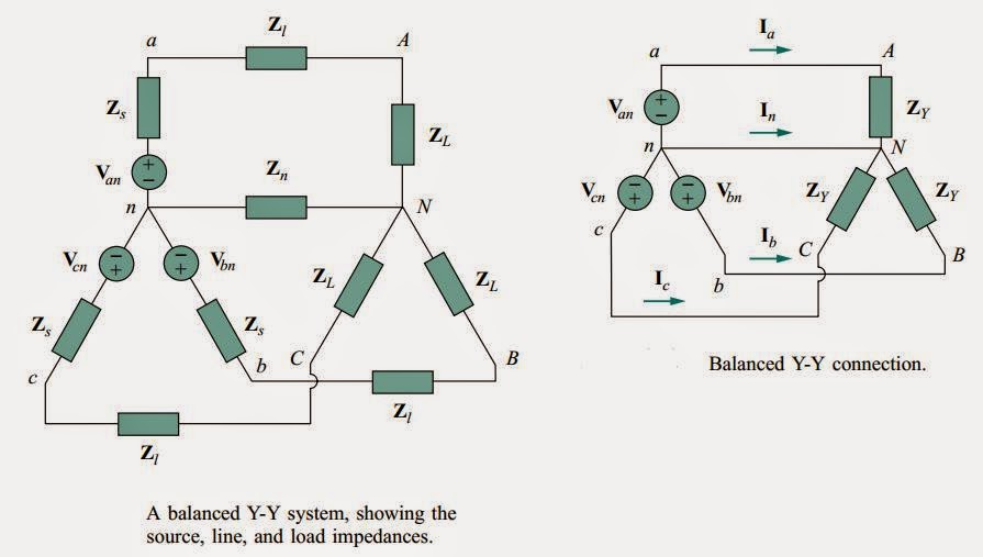
  • Balanced Wye-Wye Connection
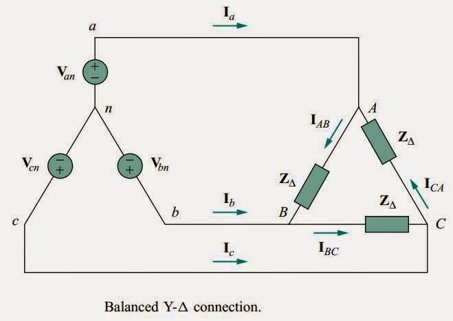
  • Balanced Wye-Delta Connection

  • Balanced Delta-Delta Connection

  • Balanced Delta-Wye Connection


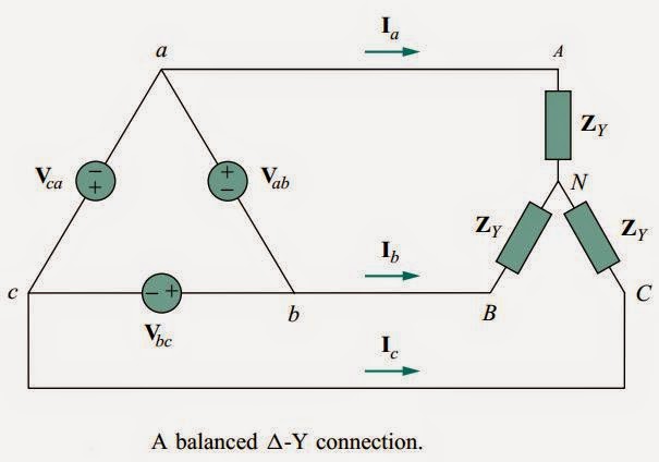
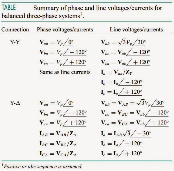
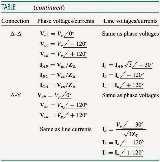
Table below presents a summary of the formulas for phase currents and voltages and line currents and voltages for the four connections. Students are advised not to memorize the formulas but to understand how they are derived. The formulas can always be obtained by directly applying KCL and KVL to the appropriate three-phase circuits.


Learning:
  • I learned that the generator is consists of rotating magnet.
  • For Wye connection IL=Ip and VL=(square root of 3)Vp.
  • For Delta connection VL=Vp and IL=(square root of 3)Ip.
  • Balanced phase voltages are equal in magnitude and are out of phase with each other by 120
  • Abc sequence is known as positive sequence.
  • Acb sequence is known as negative sequence.

Videos:

For more information, watch the video below:


That's all. Thank You for visiting my blog.
GOD Bless! :)


By:
AYALA, ARNY  S.   BSECE -3
ECE 321
Professor:
ENGR. JAY S. VILLAN, MEP - EE


10th Week: "Power Factor & Complex power"

"Power Factor"


We see that if the voltage and current at the terminals of
a circuit are,


v(t) = Vm cos(ωt + θv)
and
i(t) = Im cos(ωt + θi)


The average power is a product of two terms. The product Vrms Irms is known as the apparent power S. The factor cos(θv − θi) is called the power factor (pf).


S = Vrms Irms

The apparent power (in VA) is the product ofthe rms values ofvoltage and current.

The power factor is dimensionless, since it is the ratio of the average power to the apparent power,

pf =P/S= cos(θv − θi)

The angle θv − θi is called the power factor angle, since it is the angle whose cosine is the power factor.


The power factor is the cosine ofthe phase difference between voltage and current. It is also the cosine ofthe angle ofthe load impedance.


"Complex Power"


Power engineers have coined the term complex power, which they use to find the total effect of parallel loads. Complex power is important in power analysis because it contains all the information pertaining to the power absorbed by a given load.


Complex power (in VA) is the product ofthe rms voltage phasor and the complex conjugate ofthe rms current phasor. As a complex quantity, its real part is real power P and its imaginary part is reactive power Q.


Introducing the complex power enables us to obtain the real and reactive powers directly from voltage and current phasors.


It is a standard practice to represent S, P, and Q in the formof
a triangle, known as the power triangle, shown below,


Learning:
  • Real Power (P) in measured in W, Reactive Power (Q) in VAR, and Apparent Power (S) in VA.
  • For Power Factor (PF), when theta increases PF decreases, and when theta decreases PF increases.

    Reactive Power:
  • Q = 0 for resistive loads (unity pf).
  • Q < 0 for capacitive loads (leading pf).
  • Q > 0 for inductive loads (lagging pf).


Videos:

For more information, watch the video below:


That's all. Thank You for visiting my blog.
GOD Bless! :)


By:
AYALA, ARNY  S.   BSECE -3
ECE 321
Professor:
ENGR. JAY S. VILLAN, MEP - EE


Monday, March 16, 2015

9th Week: "AC Power Analysis"

"AC Power Analysis"

Our study in ac circuit analysis so far has been focused mainly on calculating voltage and current. Our major concern in here is power analysis.

Instantaneous and Average Power

The instantaneous power p(t) absorbed by an
element is the product of the instantaneous voltage v(t) across the element and the instantaneous current i(t) through it. Assuming the passive sign convention,


p(t) = v(t) i(t)
Where,
v(t) = Vm cos(ωt + θv)
i(t) = Im cos(ωt + θi)


Average Power

The average power is the average of the instantaneous power over one period.


Maximum Average Power Transfer
 

We solved the problem of maximizing the power delivered by a power-supplying resistive network to a load RL. Representing the circuit by its Thevenin equivalent, we proved that the maximum load if the load resistance is equal to the Thevenin resistance RL = RTh. We now extend that result to ac circuits.


In rectangular form, the Thevenin impedance ZTh and the load impedance ZL are,


ZTh = RTh + jXTh

ZL = RL + jXL

For maximum average power transfer, the load impedance ZL must be equal to the complex conjugate ofthe Thevenin impedance ZTh.


Effective or RMS Value


The effective value of a periodic current is the dc current that delivers the same average power to a resistor as the periodic current.


The effective value of a periodic signal is its root mean square (rms) value.


Learning:
  • Power analysis is another chapter and view of understanding in our class since it has lesser circuit analysis. Power is the most important quantity in electric utilities, electronic, and communication systems, because such systems involve transmission of power from one point to another.


Videos:

For more information, watch the video below:


That's all. Thank You for visiting my blog.
GOD Bless! :)

By:
AYALA, ARNY  S.   BSECE -3
ECE 321
Professor:
ENGR. JAY S. VILLAN, MEP - EE


Sunday, February 15, 2015

8th Week: "Thevenin's Theorem - AC"

"Thevenin's Theorem"


Thevenin’s theorem is applied to ac circuits in the same way as they are to dc circuits. The only additional effort arises from the need to manipulate complex numbers. The frequency-domain version of a Thevenin equivalent circuit is depicted in Figure below, where a linear circuit is replaced by a voltage source in series with an impedance.


Example:


Learning:


  • The process that are used in DC analysis is the same with the AC analysis.


Videos:


For more information, watch the video below:


That's all. Thank You for visiting my blog.
GOD Bless! :)

By:
AYALA, ARNY  S.   BSECE -3
ECE 321
Professor:
ENGR. JAY S. VILLAN, MEP - EE


7th Week: "Source Transformation - AC"

"Source Transformation"


As figure below shows, source transformation in the frequency domain involves transforming a voltage source in series with an impedance to a current source in parallel with an impedance, or vice versa.


However, we should keep the following points in mind when dealing with source transformation.


  1. Note from Figure above that the arrow of the current source is directed toward the positive terminal of the voltage source.
  2. Note that source transformation is not possible when R = 0, which is the case with an ideal voltage source. However, for a practical, nonideal voltage source, R = 0. Similarly, an ideal current source with R = ∞ cannot be replaced by a finite voltage source.

Example:


Learning:


  • The process that are used in DC analysis is the same with the AC analysis.


Videos:


For more information, watch the video below:


That's all. Thank You for visiting my blog.
GOD Bless! :)

By:
AYALA, ARNY  S.   BSECE -3
ECE 321
Professor:
ENGR. JAY S. VILLAN, MEP - EE


6th Week: "Superposition - AC"


"Superposition Theorem"

Since ac circuits are linear, the superposition theorem applies to ac circuits the same way it applies to dc circuits. The theorem becomes important if the circuit has sources operating at different frequencies. In this case, since the impedances depend on frequency, we must have a different frequency-domain circuit for each frequency.


Steps to Apply the Superposition Principle:


  1. Turn off all independent sources except one source. Find the output (voltage or current) due to that active source using nodal or mesh analysis.
  2. Repeat step 1 for each of the other independent sources.
  3. Find the total contribution by adding algebraically all the contributions due to the independent sources
Example:


Learning:


  • The process that are used in DC analysis is the same with the AC analysis.


Videos:


For more information, watch the video below:


That's all. Thank You for visiting my blog.
GOD Bless! :)

By:
AYALA, ARNY  S.   BSECE -3
ECE 321
Professor:
ENGR. JAY S. VILLAN, MEP - EE


Sunday, December 21, 2014

5th Week: "Mesh Analysis - AC"

 "Mesh Analysis"


Kirchhoff’s voltage law (KVL) forms the basis of mesh analysis.

Example:

The circuit shown is operating in the steady state.
Determine the four mesh currents.


First, convert all values to phasor notation.


Next, perform the mesh analysis.

Since dependent sources are present, define the parameters upon which they depend in terms of the mesh currents.
i5 = IC - ID
VL = j1K(IA - IB)
Since current sources are present, express their values in terms of the mesh currents, then form supermeshes.
500m0° = IC - IA
500m0° = - IA + IC (Equation 1)

12 i5 = - IB
12 (IC - ID) = - IB
0 = IB + 12 IC - 12 ID (Equation 2)


Now write KVL around each remaining mesh and supermesh.
Supermesh A/C
6 VL + j1K(IA - IB) - j200 (IC - ID) + j5K IC + 10K IC + 4K IA = 0
6 j1K(IA - IB) + j1K(IA - IB) - j200 (IC - ID) + j5K IC + 10K IC + 4K IA = 0
0 = (4K + j7K) IA - j 7K IB + (10K + j4800) IC + j200 ID (Equation 3)
Mesh D
0 = - j400 (ID - IB) + 1K ID - j200 (ID - IC)
0 = j400 IB + j200 IC + (1K - j600) ID (Equation 4)
Inserting Equations 1 through 4 into the calculator and letting it do the difficult part yields
IA = 429 m169°
IB = 337 m127°
IC = 113 m45.8°
ID = 120 m59.2°
Converting back to the time domain gives
IA(t) = 429 cos (10000 t + 169°) mA = - 429 cos (10000 t - 11°) mA (Either form acceptable)
IB(t) = 337 cos (10000 t + 127°) mA = - 337 cos (10000 t - 53°) mA (Either form acceptable)
IC(t) = 113 cos (10000 t + 45.8°) mA
ID(t) = 120 cos (10000 t + 59.2°) mA


Reflection:


  • I learned that all the concepts and process in solving the unknowns in Ac Analysis are the same with Dc Analysis. It only involves complex numbers.


Videos:

For more information, watch the video below:


That's all. Thank You for visiting my blog.
GOD Bless! :)

By:
AYALA, ARNY  S.   BSECE -3
ECE 321
Professor:
ENGR. JAY S. VILLAN, MEP - EE